Brushed DC Motors and How to Drive Them
By David Birks, Applications Engineer, Diodes Incorporated
DC electric motors have been around for nearly two hundred years, with a steady series of refinements in that time. More recently, brushless DC motors have become increasingly popular but for many applications brushed DC motors are still the right choice. Brushed motors are lower cost and are simpler to drive, so they remain a popular option.
In this article, we’ll explain the basics of brushed DC motors, and then look at the circuitry required to drive them. We’ll also introduce brushless DC motors and their pros and cons.
Brushed DC Motor Basics
Going back to basics, the fundamental principle of an electric motor is, of course, that it converts electricity into motion. It does this through the interaction between magnets, one of which is typically created by passing a current through wire bound around a ferrite core. The current flowing through the wire generates the second magnetic field. This interacts with the primary magnetic field to create an opposing force that moves one part of the motor, usually causing it to rotate around an axle.
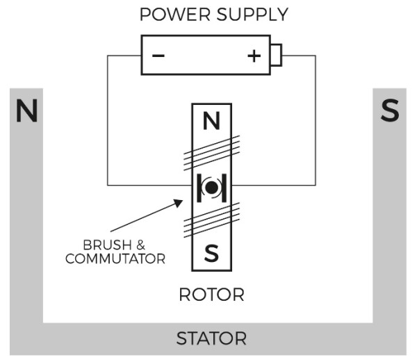
Brushed DC motors consist of four key components; the stationary magnet (called a stator), the rotor, the commutator and the brushes (see Figure 1). The rotor consists of one or more windings of wire wrapped around a core made of a ferrous metal, usually iron, and connected to power with a metal ‘brush’. When we send current through the rotor windings, the field generated interacts with the stator's field and creates the force that turns the rotor. The stator can be a permanent magnet or electromagnet, depending on the requirements of any particular application.
That’s all very well but if we just used regular wires to connect the rotor windings to the power supply, once the rotor has turned far enough its magnetic force would effectively reverse direction – so the rotor would just move back and forth, instead of rotating in one direction.
To fix this we use the commutator, which is a conductive copper sleeve around the axle of the rotor, physically and electrically divided into segments. As the commutator rotates it connects and disconnects these segments through the brushes, applying power to different pairs of segments. This causes the polarity of the magnetic field to reverse each time the motor rotates 180º, resulting in smooth and continuous rotation.

Figure 1: Two Pole Brushed Motor
The Alternative: Brushless DC Motors
As its name suggests, a brushless DC motor has no brushes. Instead it uses transistors in the electronic control circuitry to apply and remove power to the rotor's wire, producing an alternating current from a DC supply to reverse the current on each half-cycle, achieving continuous rotation.
Brushless DC motors are typically smoother and more efficient than brushed motors, have higher torque-to-power ratios and offer higher speeds with more precise control. With no wear on a brush or commutator, they need less maintenance and have a longer operational life. However, one of the main drawbacks of the brushless motor is cost: of the motor itself, and of the more complex drive circuitry that’s needed.
To provide continuous motion, the brushless motor’s controller reverses the direction, or phase, of the current each time the motor rotates 180 degrees, or another fixed amount such as 120 degrees for a 3-phase motor.
Varying the control voltage may be achieved with analog components, or digitally using an FPGA or microcontroller. The control circuitry needs to be aware of the relative angular position of the motor, so it can activate the correct phase at the right time. This can be achieved with sensors, by using an optical encoder or Hall effect sensor, or without sensors by inferring the rotational angle from the back EMF generated by the magnetic field. In either case, an all-in-one motor driver is often used which integrates the required functions into a single chip.
Drive Circuits for Brushed Motors
In principle, as discussed above, a brushed motor does not require an external controller, as the change of magnetic field polarity is implemented through the brushes making and breaking the electrical pathway through the windings, achieving continuous rotation in one direction.
For some applications, that’s good enough. But if we want to be able to change the speed of the motor, or reverse the direction of rotation, we need a drive circuit. This can be as simple as just reversing the direction of current flow to make the motor turn the other way.
To change speed we could alter the voltage, using a potential divider – with speed being proportional to voltage. However, reducing the voltage in this way is inefficient, as a voltage divider does not reduce the total current flowing. To overcome this, pulse width modulation (PWM) is often used, which involves rapidly switching the current off and on to reduce the ‘average’ voltage across the motor.
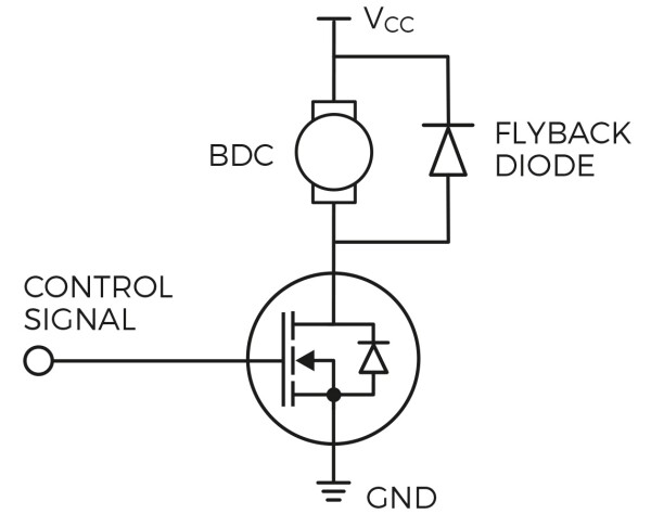
Let’s look at an example of a simple single-direction application, such as a toy. For this, we only need a single transistor and a flyback diode, which provides a route to dissipate the back EMF that could otherwise cause damage (see Figure 2).
To enable the speed to be varied, we need a transistor that can deliver the required power and can be switched on and off by a control signal. An example of this is the DMTH4008LFDFWQ from Diodes Incorporated, a rugged MOSFET device that operates at up to 175ºC. The device offers high power density, with up to 40V and 11.6A being handled in a compact 2mm x 2mm package.

Figure 2: Single Direction Brushed DC Motor Control
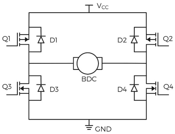
If changing the motor's direction of rotation is required, it can be achieved using an ‘H-bridge' circuit, so called because it uses four transistors to control the flow of current (see Figure 3). When the two transistors Q1 and Q4 are switched on, current flows through the motor (labelled ‘BDC’ in Figure 3) from left to right, making it rotate. Switching Q1 and Q4 off, and turning Q2 and Q3 on, causes the current to flow from right to left through the motor, causing it to rotate in the opposite direction. Figure 3 also shows that we still need a flyback diode for each transistor, as in the single-transistor circuit discussed earlier. In practice, the body diode of the transistor provides this functionality.

Figure 3: H-Bridge Gate Arrangement
There are now devices available that integrate all four transistors of the H-bridge into one package, such as the DMHC4035LSDQ. This forms an H-bridge that can switch up to 3A. It is provided in the SO-8 package and is qualified for automotive applications, based on the rigorous AEC-Q101 standard. This device can also be used to control a single-phase brushless motor.
Conclusion
Brushed DC motors may seem less glamorous than their brushless cousins but they deliver reliable, proven performance that needs less complicated drive circuitry – keeping overall costs to a minimum.
Choosing the right motor for any given application depends on the specific requirements of that application. Is precise control of the motor’s position required, with the smoothness of motion offered by brushless motors, or can a simpler, lower cost brushed alternative provide a better solution? Is it important to avoid wear and maintenance, which a brushless motor can deliver, or does the application's motor operate so rarely that deterioration of the brushes and commutator is a low priority?
If the application does not justify the higher cost and complexity that come with the features offered by a brushless motor, then a brushed DC motor, coupled with the right drive circuit design, can still provide a very appealing solution.
